Controlling Speed of a motor | Pulse Width Modulation on ESP 8266 | L298N motor driver
Pulse Width Modulation PWM on ESP8266
In this tutorial we will learn about pulse width modulation (PWM). PWM is used to turn on and off a device at a rapid pace to stimulate decrease voltage and reduce power intake. In this case, we will drive a motor at reduce speeds. The width of the pulse will determine the amount of time the power needs to be on for the device. Hence the name Pulse Width Modulation.
1. BO motor and wheel
2. NodeMCU
3. Power supply to power L298N motor driver
4. Potentiometer 10K
5. Jumper wires
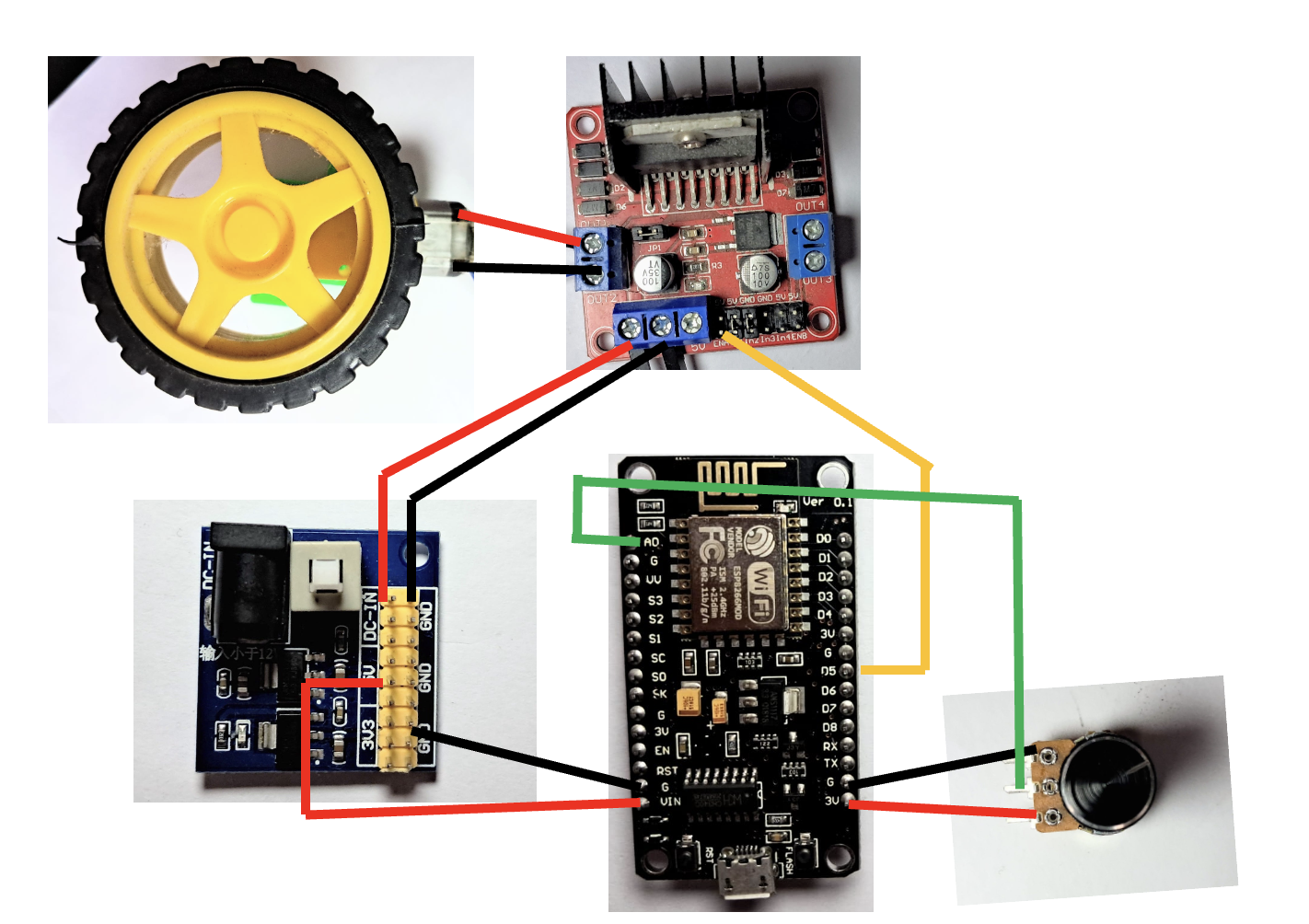
Connections
Power Module L298N Driver ESP Potentiometer BO Motor
12V 12V
Gnd Gnd Gnd Gnd
5V Vin
3.3V Vcc
A0 Middle pin
En1 D5
M1 and M2 + and -ve terminal
We will use D5 pin to generate pulse width modulated signal connected to Enable pin of L298N driver.
In this IN1 and IN2 of the motor diver are connected to 5V and Gnd respectively.
Code
int sensorPin = A0;
int value = 0;

void setup() {
}

void loop() {
  value = analogRead(sensorPin);
  delay(10);
  analogWrite(D5, value/4 - 1);
}
When you move the potentiometer, ESP will read the value and convert it to digital
unit to be used to set duty cycle at D5 pin.


Comments
Post a Comment